PWM Working Principle Pulse Width Modulation How It Works Circuit Diagram However, one of the most preferred and simple ways is by using a Pulse Width Modulation (PWM) circuit. The PWM (Pulse Width Modulation) is a technique used in driving inertial loads for a long time. The use of pulse width modulation in controlling motor drivers comes with several advantages.

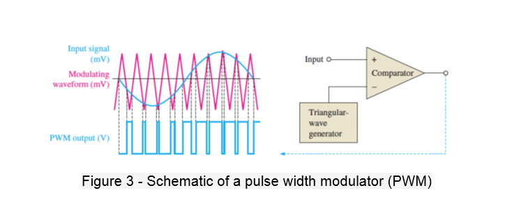
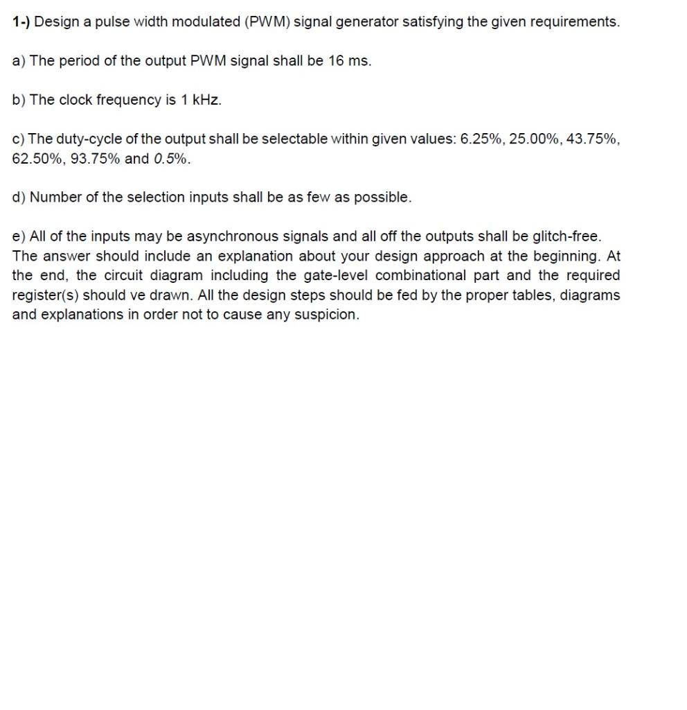
Pulse width modulation (PWM) is a technique used to precisely control analog devices with a digital signal. A pulse width modulation signal consists of electronic pulses that are used to mimic a changing analog voltage.
Pulse Width Modulation PWM fully Explained with calculation & example Circuit Diagram
Overview This document discusses basic concepts of pulse width modulation (PWM) and how to use the NI myDAQ or ELVIS II series to generate a PWM signal. Description Pulse width modulation (PWM) is a technique in which a series of digital pulses is used to control an analog circuit. The length and f
Pulse width modulation PWM: PWM stands for pulse width modulation which consists of a square wave with the help of which we can control the up or high time. It is simple but digital way to control the digital signals that we use to vary the energy that is send to a load or to encode information within the signal.
Building a Simple Pulse Width Modulation (PWM) Generator Circuit Diagram
If you're into electronics, you've probably heard of Pulse Width Modulation (PWM). It's a technique used to control the power delivered to electrical devices, especially motors, LEDs, and other components that require precise control. Today, we're going to dive deep into building a simple PWM generator. Whether you're a beginner or an experienced tinkerer, this guide will walk you through the