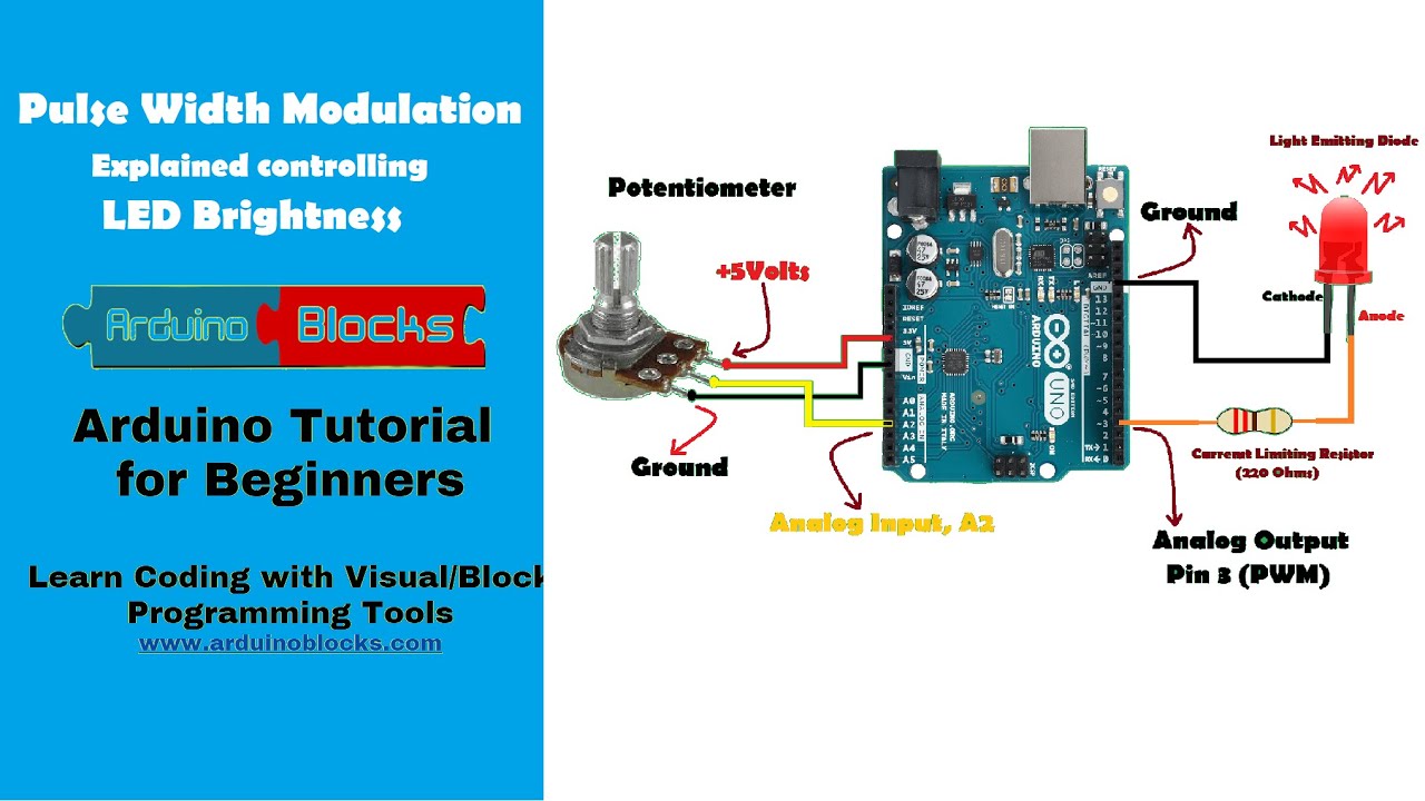
Home Automation using arduino bluetooth Circuit Diagram
Home Automation using arduino bluetooth Circuit Diagram However, what we have managed to achieve so
Dream Big, Explore Beyond Ayla Harper.
Smart home circuit Circuit Diagram This home automation circuit diagram is the step-by-step guide to
Vehicle Charging Circuit Diagram In our circuit, a 230v/12--12v transformer is used to execute the
Face Recognition based Attendance System Circuit Diagram How do Face Recognition based Attendance Systems Work?
How to Make Touch Switch Sensor 7 Steps Circuit Diagram In this video, we are
Voice Activated Home Automation Circuit Diagram To build your local AI voice assistant, you'll need
Home smart speaker Generate AI Circuit Diagram Irvinei AI Powered Touchscreen Doorbell: Redefining Home Automation.
Automated Inventory Management What Is It And How Can It Help Circuit Diagram Assess Your
equalizer circuit Audio Circuits Nextgr Circuit Diagram portable speakers, headphones, and home audio systems. The
09A Power Supply Variable Voltage Current DIY Circuit Diagram I easily get continuously adjustable output
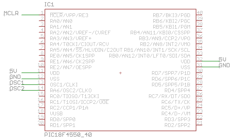
Electrical And Electronic Engineering Basic Circuit For Microcontroller Circuit Diagram Pointing fingers doesn't help a
HOW TO MAKE a BLUETOOTH CAR 7 Steps Circuit Diagram Want to control a robot
Mini Multi Stage Peltier Cooler Module Thermoelectric Module Circuit Diagram However, challenges Peltier cooling technology
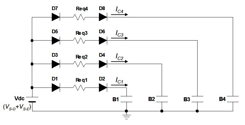
The circuit block diagram of the frequency synthesizer Circuit Diagram The frequency-divider modulus N have
How can i make a easy op amp circuit Circuit Diagram Op amp IC1 is
BENEFITS Of IOT BASED HOME SECURITY SYSTEM by PsiBorg1 Circuit Diagram Building a smart home
Circuit Board Repair Analysis Circuit Diagram BEST PCB repair kits give you the tools you
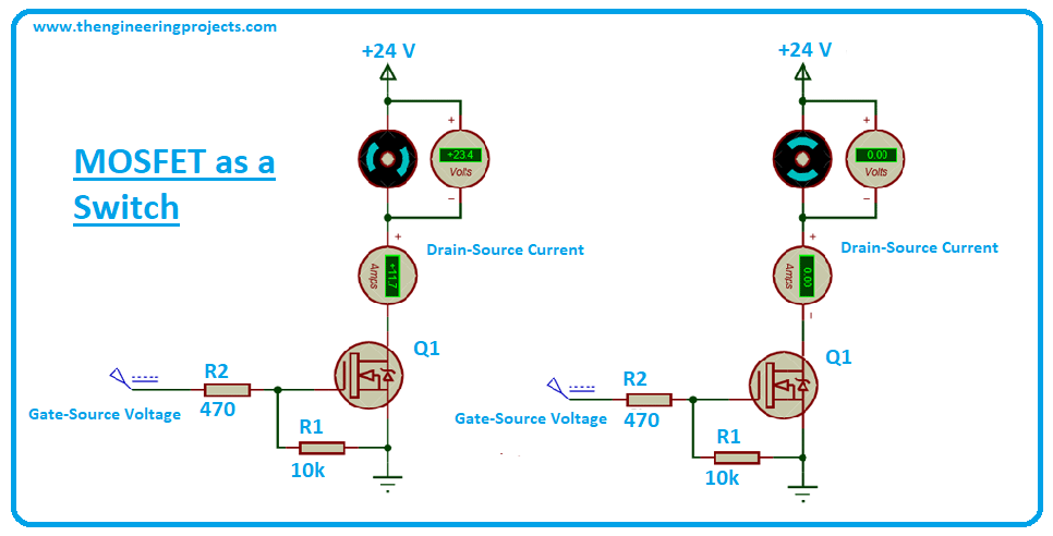
MOSFET WHAT A MOSFET IS AND HOW IT WORKS Circuit Diagram MOSFETs are the most
Stepper motor Arduino Arduino projects Circuit Diagram Stepper motors are available in several versions and
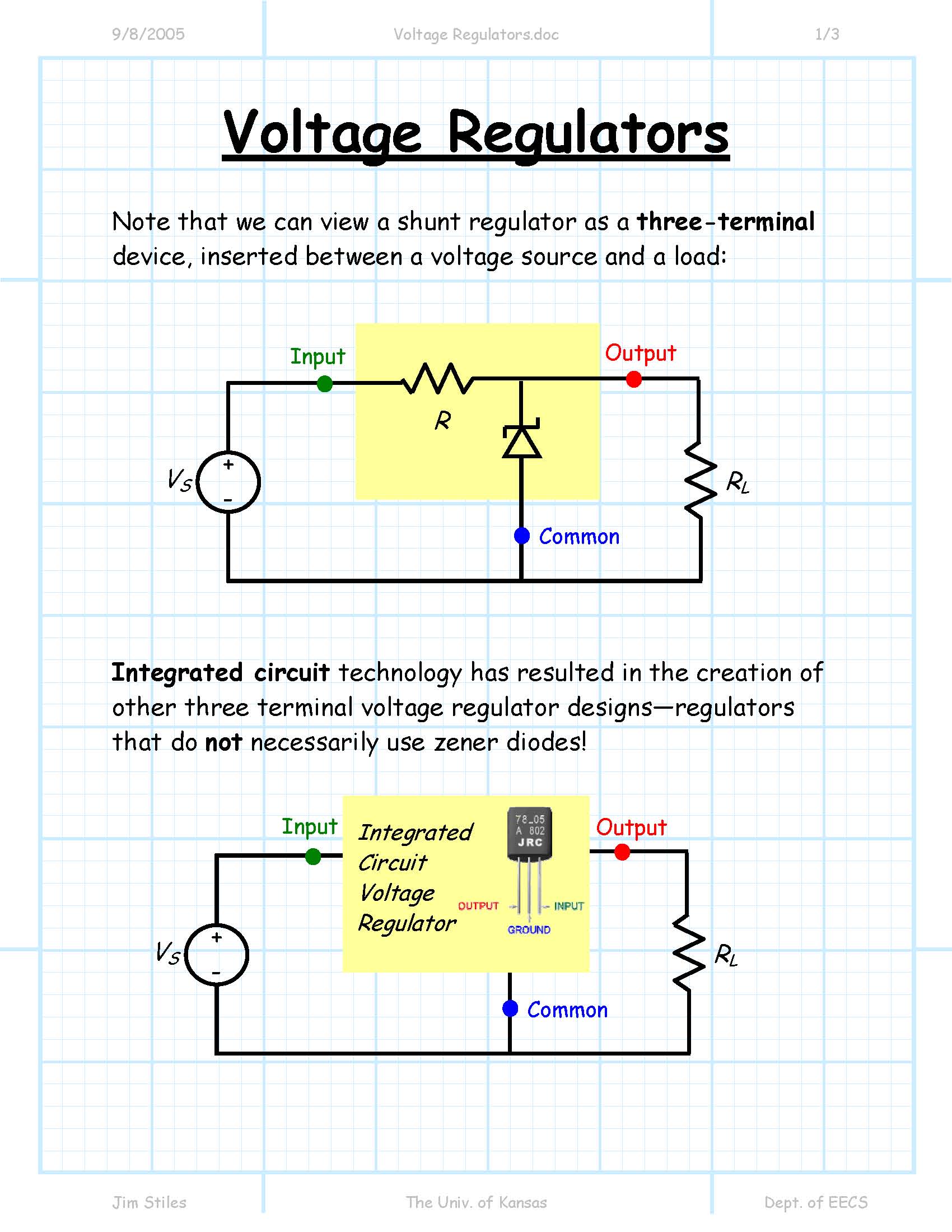
Index of jstiles312handouts Circuit Diagram Here we used a Zener as the reference and the
Solved Draw the logic gate diagram of the logic below Circuit Diagram If you want